Some Software Success

June 21st, 2008

As I am working through the hardware side of this CNC project I have been trying to figure out the software that will enable me to prep my designs for the machine. Really, this has been almost a bigger hurdle for me, though I realize once I get a tool chain figured out it will probably flow without difficulty.

One problem, is sorting through the tons of software that is available. Every package seems to have a different and often funky-clunky GUI with a different tack on how to organize the elements. After trying several methods some of the process is starting to jell.

It seems like there is no do all box for this process at least not yet. You have to find something to do drawings in, then find something to create tool paths and create gcode. Really, I also wanted something that could take images, like bmps, jpgs, etc and prep them for the machine, this would allow me to start with a drawing on actual paper.

What seems like it may work for now, is Inkscape to do tracing, converting from Raster to Vector, or just doing Vector drawings with. Save as DXF, looks like the linux version of Inkscape is the only one that will write AutoCad style DXF files, watch out for this if you try it. After I have the DXF I use CamBam to generate tool paths and GCode.

I have been trying to convert this bitmap that I found via google images for weeks now. So far this is the first method that has worked from start to finish. Seems remarkably easy now, but let me tell you, it was confusing getting here.

Another promising solution that I will probably also use is the GMAX CNC-toolkit combination. GMax is a 3D game scene builder. There is a script called CNC toolkit that you can plug into this software and use to generate toolpaths and gcode. All this ends up being free if you can figure out how to do it. There is a site with documentation and links to the software CNC4free.org

Also check out Qcad for an easy to use 2D CAD drawing software. Perfect for drawing up a part with precision for the machine. Saves as DXF so that other CAM processing software can open them.

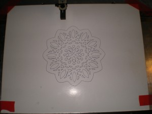
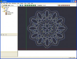
Here are some screen shots of the original image one with tool paths:

The original image is a mandala from The Mandala Coloring Book
by Monique Mandali

First the image was traced with the linux version of inkscape, the resulting image looks almost exactly like the original, however it is now made up of vector line segments instead of dots, all the better to do math on! The image was saved as a dxf in autocad format and then opened with CamBam.

Mandala converted to tool paths with cambam

Once you have the tool paths and cutters defined its a one click operation to generate the Gcode for the machine.

This is a copy of the mandala gcode if you want to run or look at in a gcode simulator, may have to do just a bit of tweaking with a text editor to make it suite your particular machine, spindle, feedrate etc…

A Donation Wow!!!

June 21st, 2008

A reader of my progress on the OZO machine has offered to donate a compressor for the cause (see comments on last post). This is fantastic news, as the tank I have been using is not sealed enough to hold pressure for long periods. If I pressurize to about 80 PSI the tank holds air for about two days. I have not made a serious attempt with soapy water and a brush to find the leaks though.

It doesn’t take many trips out of the house to find air, to realize this idea is not going to work. The compressor will allow me to keep the tank topped off and may even provide auxiliary vacuum for a hold down platform.

I’ll post some pictures when the compressor arrives,

Thanks again Michael, this is very kind of you and a real surprise for me.

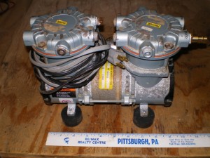
EDIT: Here are some pics of the compressor once I got it in the mail

I added the feets as I had them laying around, note how small this cute little guy is.

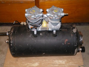
Here it is sitting on the tank, for perspective, tank is about 1.2 cubic feet and this little pump, pressureizes it to 60psi in about 10min or so…

The compressor is made by GAST, this is a link to the DataSheet

The info is not for this exact pump as the model number is SAA-PXXX-NA

and it states “Derivative Prototype”

Air for the Spindle

June 17th, 2008

Over the weekend, I managed to scrounge together enough plumbing pieces to resurrect an old air tank I have into a working portable air supply. Basically its a tank with air gauge, pressure relief, hose, quick connect, and valve that I can fill up and then attach to the spindle.

The idea was that I would get multiple open/close cycles on the collet without the need for an air compressor. While I managed to get the tank built and worked the collet several times, its still not completly tested.

One flaw in the plan was that they removed the free air line that was a couple of blocks from my house. So, I had to drive around and the only place I found near my house, has a pretty crappy compressor that would only pressurize the tank to about 40 psi.

I was able to actuate the compressor many times with this weak fill however. So… it remains to be seen, if I can fill up the tank and use it for about a week. Still even if it doesn’t work, I am not out much money and it will be a portable tank for filling tires etc…

My Kingdom For a Schematic

June 11th, 2008

You never know how handy a schematic is until you are without one. I tried various ways of enabling and controlling the spindle without success. Part of it was confusion with EMC however most of it was because I was unsure of the layout of the encoder board.

I knew that it boiled down to the signals being presented to the Enable and Vtrip input pins on on the Spindle control board. Enable needed to be held high and the voltage at Vtrip would control the speed of the spindle. I proved that to myself by removing the encoder board and hot wiring the Spindle card directly with the needed signals.

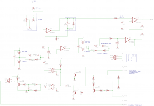
Still, I could not get the spindle to spin up with the encoder board in the machine. Finally I decided to take the time to trace out the circuit on the encoder card. It took a while, 4 opamps, 5 transistors and quite a few discretes on a double sided board can get fairly confusing. I just took it slowly worked on it a bit each evening and eventually came up with this.

Once the mysteries were revealed it was obvious that the control signals where going to have to be repetitive square waves as all the inputs ultimately go through a cap before they can induce voltage on Vtrip. Looks like there is some kind of feedback from the S1 and S2 encoder signals on the spindle itself too, so I am guessing once you set a speed it will maintain even if you encounter a load, this is good news if its true.

In the end I just removed the clamshell from the parallel port cable I was using. Removed all but the signal wires for the XYZ axis, then routed Pin1 from computer to Pin11 of the machine port. Added that control pin to my config file using stepconf, and joy oh joy. I now have control of the spindle from the computer.

Next step is air, the spindle collet opens and closes with air pressure, looks like it may finally be time to get a small compressor for the shop. 😉

Impasse

June 6th, 2008

Reviewing the EMC2 manual it seems that pins 18-25 on the parallel port or always ground. The signals I want access to next on the OZO are the encoders and the spindle control. Unfortunately the encoder signals look mapped to Parallel 20,23,24 and the likely spindle control is on Pin 11.

These pins are not going to work with the Parallel port in the computer. I may not even have enough I/O on the port to completely control this machine, however, what I really need next is spindle control, at least on off. Looks like the OZO may have had a proprietary card in the computer after all.

The new plan is to build a small converter board. I am hoping to use two wire wrap parallel port sockets, plug one end into the OZO and then map across to the plug that will connect to the computer. This way I can remap some of the OZO signals to the computer and have access to them at the port for probing etc…

We shall see!

Encoder Board

June 6th, 2008

Tried to do a bit of reverse engineering on the encoder board. Pin 1 starts on the end of the board that bolts to the machine.

Pin Signal
1 Routes to 1B and 8B on Spindle Board Ground FWD/REV
2 Signal in from actual encoder routes toSN74LS123N
3 Signal out from encoder board to Pin 20 Parallel
4 Signal in from actual encoder routes to SN74LS123N
5 Signal out from encoder board to Pin 23 Parallel
6 Signal in from actual encoder routes to SN74LS123N
7 Signal out from encoder board to Pin 24 Parallel
8 Routes to Spindle Board Pin 6B V-
9 Unknown
10 Unknown
11 Routes to Parallel Port Pin 1 and Pin 12 probable Ground
12 Routes to 1B and 8B on Spindle Board Ground FWD/REV
13 Unknown
14 Unknown
15 Routes to Spindle Board Pin 4B and 10B V+ Positive Voltage
16 Unknown
17 Routes to Spindle Board Pin 7B Vtrip
18 Routes to Spindle Board through 4.7K to Pin 9B Enable
19 Routes Parallel Port Pin 11 *****Possible Control signal for Spindle *******
20 Routes to Spindle Board Pin 2B (S1 Signal)
21 Routes to Spindle Board Pin 3B (S2 Signal)
22 Routes to 1B and 8B on Spindle Board Ground FWD/REV

Links to the data sheets for the major players on the board:

DM74LS123 Dual Retriggerable One-Shot, there are two of these, probably handling the signals from the encoders. The Q outputs of these go to the Parallel port and the B inputs go to the encoders, not sure yet how this works.

MC1458 High Performance Dual OpAmps, most likely controlling the speed of the spindle, there are two on this board.

CD4070BC Quad 2-Input Exclusive Or Gate, somehow tied with Enabling the Spindle, might be a phase detector? Square wave to enable spindle, I dunno, it gets confusing pretty quick around this thing.

The Spindle Moves

June 4th, 2008

Spent some more time with the LS7262 spindle motor chip datasheet today.  Used the drawing I made previously with the pinouts for the board and with the datasheet I tried to figure out what signals I should see on the various pins.

The first thing I noticed was that the LS7262 is supposed to be for transistors and the LS7260 is supposed to be for FETs, this is odd since the main power components on my board are obviously FETs.  Still there are some transistors (possibly gate drivers) in front of the FETs.

I noted that CS1 and CS2 where both tied low and that I was only showing two Sense pins coming out of the board.  Turned out that this was the configuration for Four Phase Operation (page 5).

Also, the Enable pin is active High and Low Disables the output.

The chip needs:

Voltage for a Logic 1 (High)  VSS-1.5V to VSS

Voltage for a Logic 0 (Low) 0V

Probing around this evening:

VSS Pin 11 to Ground: 15.0V with Small encoder card Removed

14.2V with encoder card in.

Common Pin 5 to Ground: Same as above

Brake Pin 9 to Ground: 0V

Enable Pin 10 to Ground: .5V with encoder card in 15 Volts with it out. (Hmmm!!!)

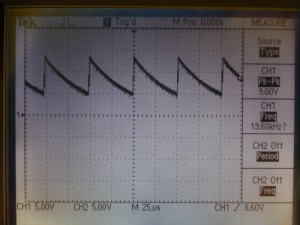
Ocillator Pin 14 to Ground: Sawtooth waveform Peak at 13.4V Floating on 4.60V (Perfect, I think)

Also, during all this probing, I noticed that the electric air valve that I think controls the spindle collet, engages with the button on the front panel only when the small encoder card is in the machines.

So, after I probe the signals and realize that all the signals are basically there, I try the spindle with out the small encoder card installed so that Enable is on and not being held low by the card.  No joy!

I decide to have a look at Vtrip and it is low.  This would indicate the spindle should be running at full speed.  I remembered at this point, somehow, that when we moved the machine a fuse cap had fallen off of one of the two fuses on the back of the machine.  I had picked up the cap and stuck it back on, at the time it hadn’t seemed to fit well.  Reinvestigating it seemed that there was a spring missing and the fuse was fitting very loose in the fuse casing.  Digging around in the surplus pile I found a small spring that fit in the cap. Once installed I tried starting the machine again, and much to my delight, the spindle motor spun up to life.  Sweet!!!

It seems there is a speed controller as part of the small encoder board, as when its installed the Spindle spins up however slows down and stops shortly.  Vtrip pin, which controls the PWM starts about 2 volts and then climbs to around 11.00 volt disabling the spindle.

Looks like the next step in all this is going to be to figure out the encoder board.  Still if I want to run the machine with the spindle now, I could do it with a small breakout board.  Transistor to control the enable pin and a voltage divider with a pot for the spindle speed control.  Looks like I am close to actually being able to cut something.

Scope Image of the Oscillator:

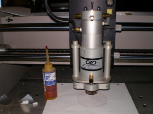
Spindle:

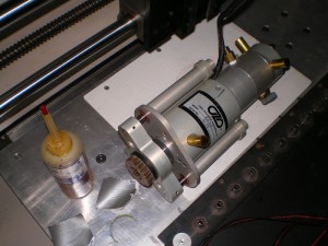
Spindle:

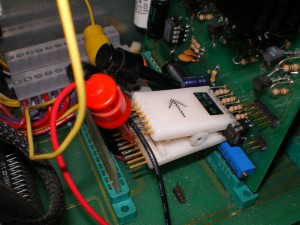
Test Jig:

Spindle Motor Controller

May 30th, 2008

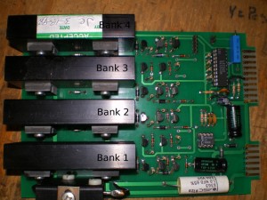
This OZO has a spindle motor, with a proprietery controller card.  This evening I took the first stab at trying to reverse engineer this circuit card.  From my research so far, I think that it may be possible.  There are 8 output devices all appear to be the same 32N20E, these are 32Amp 200Volt Power FETS, WOW!

There is an LS7262 brushless motor controller chip and a 555 timer which may provide the oscillator input for the servo controller chip.

This is a picture of the Board with the IO pins labled:

Close up of the Board with Pins Labled

Pin out:

The bottom right 5 card edge connectors seem to be associated with the output drive to the motor.

1A Power for the motor (Probably High Voltage like 30 Volts)

2A Fat Trace to FET Bank 4

3A Fat Trace to FET Bank 3

4A Fat Trace to FET Bank 2

5A Fat Trace to FET Bank 1

6A Ground (Also connects to 1B)

The upper card edge connector appears to be IO for the LS7262 Chip

1B Ground (Also connects to 6A)

2B Connects to S1 on LS7262 (PIN 15)

3B Connects to S2 on LS7262 (PIN 16)

4B VSS which is actually V+ for the LS7262 (PIN 11)

5B Brake of the LS7262 (PIN 9)

6B -V of the LS7262 (PIN 18) Also connects to the CS1 and CS2 and Ground

7B VTRIP of LS7262 (PIN 13)

8B FWD/REV of LS7262 (PIN 19)

9B ENABLE of LS7262 (PIN 10)

10B V+ also goes through Pot to open jumper pin to CS1

It will take some more reading of the data sheet to figure out what signals EMC needs to send to control the servo.  It seems like it revolves around the Vtrip pin as far as speed control.  That pin seems to go to one of the IO pins on the other proprietery card.  It will take some more time to begin to understand that card.  I thought that it was mainly centered around the  encoders and limit switches, now I am beginning to question that assumption.

Its nice to think there may at least be hope of getting the existing orginal spindle going again.  We shall see…

Tuning the Machine

May 29th, 2008

OK, now to get the OZO purring like it otter…

First I visited EMC Wiki and followed the latency test directions.

These directions are basically the same ones in the integrators manual, however there are a couple of new wizards mentioned on the Wiki page, that came out with release 2.2.2. I first ran the latency test the old fashioned way, and then the newer way by just typing latency-test into a terminal.

The results:

Old way reports 22,778 nS

New way jitter reports 20,020 nS

I decided that I would take an average 20,544 nS and round down to 21 uS

Now to figure out thread pitch, using the method described here I came up with:

X Pitch Count=5 Pitch=.200 in.

Y Pitch Count=5 Pitch=.200 in.

Z Pitch Count=8 Pitch=.125 in.

My motors are 1.8 degree per step 200 steps per revolution.

From the best  manual I could find, my stepper controller requires 15 uS step hold time, there is no timing information for the direction pin. So, rather then configure step time, step space, direction hold, direction setup times individually, I will use 15uS + 21uS = 36uS as the Base Period for now.

The driver I have can only run full step and half step, I am going to assume half step for now as I can not easily access the jumpers in order to verify.

Next I ran the stepconf wizard and set the IO pins for the parallel port and tried to fine tune and measure each axis.  I followed the directions in this PDF as well as this Tutorial.  There was some error with the Z travel distance and I had to run the program again after the initial configuration.  I was able to edit just the sections of the Z axis that I wished with out issue.  Really nice job on the Wizard/Druid thanks to EMC team.

In the end I decided on 2 revolutions per inch on the Z-Axis, had to open up the motor housing, measure with a caliper and then rotate the stepper shaft by hand.  Seems to be scaled right with what I can measure at this point.

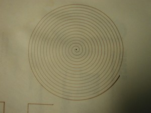
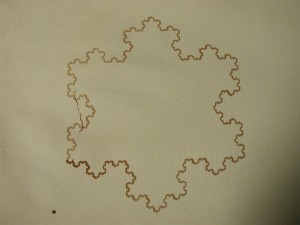
I plotted a couple of the examples from the EMC examples directory just try everything and this is what the machine drew, using the pen tool on the Z-axis.

It Moves…

May 20th, 2008

Just a quick post, I am very happy.

This evening I finished tracing out the main signals to the parallel port. Copied the default files from emc sample_configs into my home directory and edited the default pinout hal file to reflect my findings. Changed just a couple of things in the default stepper ini mostly just to reflect filenames, and …

Figured what the heck, lets give it a go. I was a little nervous about trying to run the machine without isolation, and the ground traces don’t line up between the computer and the machine, but hey!!!

It worked!!!

I had to invert the direction pin for the X axis, but that was a simple edit of the pinout file. Sweet! I ran the test gcode, and moved the machine around manually. Its way out of tune, the scale is way off. However, all of that can be fixed. At least it moves, and thats a very big deal indeed!

EMC Documentation list the very nice User Manual as Well as Integrators Manual. The Integrators manual has a section on tuning stepper motors.

Some Notes from a person explaining how they set up there steppers and adjusted for scale. Seems like the variable to change is INPUT_SCALE in the ini file.