EMC Configuration

May 18th, 2008

I have decided to use linux EMC as the initial control software.  First I love linux, second this is fantastic software for machine control.  It runs with on top of a real time kernel and has a nice GUI interface called axis.  As I ramp up on GCODE and CAM/CAD software I have been using AXIS to simulate my produced code.  Its all been working very well.  I have a bit of experience with EMC in the past, using it to help some Senior Design Students retrofit an old StarTurn CNC Lathe.  So, for now its an obvious choice for machine control.  I’ll use this post to document some of the install notes and configuration changes.

Using Ubuntu Dapper LTS for now, even though Hardy Heron LTS is recently out.  My machine for control purposes right now is an older 700Mhz Pentium.  Dapper has been running on this machine for over a year, so for now, just installing EMC along side, will reboot into the realtime kernel to control the machine.

First Step:

Used the install script from the EMC website, changed permissions to executable and it ran fine rebooting into 2.6-15 Magma realtime kernel EMC2 works!

Next Step:

Review standard_pinout.hal to see how its configured by default standard_pinout
A little Research

May 18th, 2008
  • Proxy Statement This is Document outlining the exchange of the company to Jot Engineering gives interesting details about the number of this type of machine and cost etc…
  • OZO Support Some ex OZO technicians that will repair and work on these machines, they have a history page images of the machines and, sell replacement parts, software.
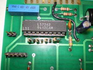
  • Servo Spindle Motor Driver Chip DataSheet link for the chip that controls the spindle motor drive electronics
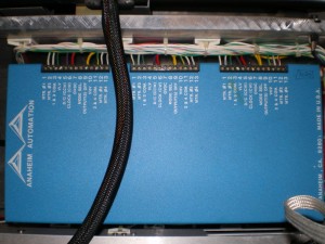
  • Anaheim Automation The people that make the stepper Motor Controller Module
  • User Manual Link to a user manual that is very similar to the controller box in the OZO machine not the same one, however email to Anaheim yielded no return on the exact model number of the box thats in the machine, so far this is the best reference for the hookup.
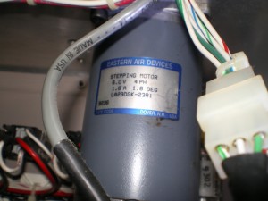
  • Stepper Motor A catalog from EADmotors Eastern Air Devices, list the stepper motor in the machine. model LA23DGK-23 in unipolar configuration (6 leads) (6.00 VDC) (1.76 amps) (3.40 ohms) (8.4 mH) (168 oz-inch) in bipolar configuration (8.50 VDC) (1.25 amps) (6.80 ohms) (33.4 mH) (210 oz-inch)  Not sure right now the motors are in bipolar or unipolar configuration.
  • 4N26 Opto-Isolator the chip I plan on using to isolate the computer parallel port from the machine controller.  Mainly just because I have some.
  • Parallel Port Link to the Hardware Book parallel port pinout page
  • A Chart of the Pin Out of the Ozo Machine as I manage to trace out the existing connections
Pin Parallel Port OZO Machine
1 Ground Ground (Wired to Pin 1 OZO)
2 N.C. Red Unused (Wire runs to near controller N.C)
3 N.C. Purple Unused (Wire runs to near controller N.C)
4 Clock (Z-Axis) Red Clock (Z-Axis) (Wired to Pin 4 OZO
5 Direction (Z-Axis) Purple Direction (Z-Axis) (Wired to Pin 5 OZO
6 Clock (X-Axis) Red Clock (X-Axis) (Wired to Pin 6 OZO
7 Direction (X-Axis) Purple Direction (X-Axis) (Wired to Pin 7 OZO
8 Clock (Y-Axis) Red Clock (Y-Axis) (Wired to Pin 8 OZO
9 Direction (Y-Axis) Purple Direction (Y-Axis) (Wired to Pin 9 OZO
10 Probe Input Probe Input (Wired to Pin 10 OZO)
11 Y Home Switch High Open Low Closed N.C.
12 X Home Switch High Open Low Closed N.C.
13 Z Home Switch High Open Low Closed N.C.
14 N.C. Y Home Switch (Wired to Pin 11 computer)
15 N.C. X Home Switch (Wired to Pin 12 computer)
16 N.C. Z Home Switch (Wired to Pin 13 computer)
17 N.C. N.C.
18 GND N.C.
19 GND N.C.
20 GND N.C.
21 GND N.C.
22 GND N.C.
23 GND N.C.
24 GND N.C.
25 GND N.C.

Lets See Whats inside

May 18th, 2008

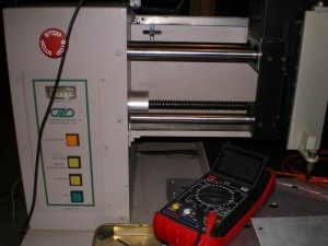
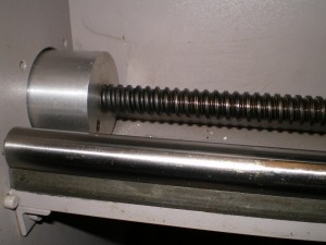
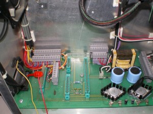
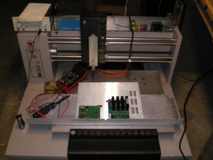
Just a few shots to document the innards of the machine. Whats really fantastic is that I found a 3rd party stepper motor driver. This should make motor drive interface at least possible to sort out. Really, I was expecting to find some proprietary hardware controlling the stepper motors, this find is a huge bonus. There is some custom hardware for the spindle motor controller, however at least one of the chips gives a great clue as to how the board might be set up. Some images to clarify the insides.

Front view with covers off testing stages:

Front Panel:

Front Panel

Close up of one of the stages drive mechanism

Stepper Motor

Controller Aneheim Automation

Spindle Motor Controller Chip

Main Board

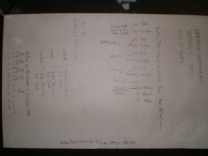
Note Sheet

–Begin CNC Rebuild–

May 18th, 2008

First Steps:

Built Metal and Wood Platform with Castors to support the machine

Cleared a Path to the machine in the Tin Shed

Friends gathered to help move the machine (very exciting)

Open machine to see whats inside…

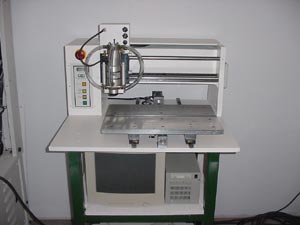
Similar Machine Model 18