Prompted by my friend Michael I decided to take another look at the encoder set up on the OZO machine.
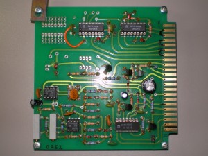
The encoder board, has the spindle signal conditioning circuit mentioned in previous post as well as two SN74LS123 Monostable Multivibrators. Its my guess that these chips act as one shots, conditioning the signals coming from the encoders. On the encoder board pictured below, pin 1 is at the top and 22 is at the bottom. Encoder signals are marked with black connecting lines.
Pins 2 – 7 are directly involved with the encoders. The even pins 2,4,6 go to the non inverting inputs on the 74LS123 chips and the outputs come from the chips to the odd pins 3,5,7. Pins 3,5,7 then connect to the parallel port pins 20,23,24 respectively.
According to the data sheet the timing appears to be set to about a 27mS pulse from the chip each time it is triggered. The timing is set with an external 82K resistor and a 1uF tantalum cap, 3 sets for each of the 3 triggers in two chips. One chip has holes where the timing could be set with external components however this is not populated on my board, and that multivibrator is not in use.
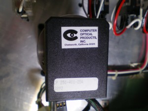
The black box encoders are made by Computer Optical Products, Inc in Chatsworth, California
From the encoder label they are CP 250-400-ODA
Corresponding to 400 steps per revolution, digital encoders with two signals out, in quadrature.
The black box digital encoders are on the X and Y axis and look like this,
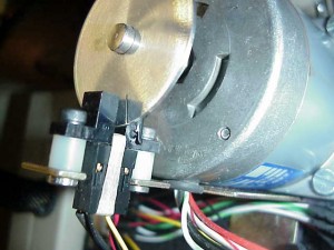
While the Z-Axis has a flat disk with a slit in it like so, (thanks for the photo Michael)
Edit: More Info discovered and added below
The signals going to the encoder board and ultimately the one shots are index signals. I think they represent full rotations of the stepper motors, but still not quite sure. If you look at the data sheet for the black box encoders they have Chan A, Chan B, and index.
The pin out in the data sheet is for the “Rear Exit Pin Option” on my machine. The A and B channels are in quadrature, 400 steps per revolution. The index I think goes by at 1 rpm. Coming into the encoder board, the index signals are about 1ms long, leaving the encoder board and going to the parallel port they are about 24ms long, consistent with the data sheet for the one shots. The Chan A, Chan B quadrature signals square wave frequency varies with the feed rate of the Axis in motion, as it should.
Good news is I discovered that the Chan A and Chan B signals route directly to the parallel port, the encoder board is not even in play so…
It shakes out like this,
X-Axis
Chan-A straight to Pin 21 parallel
Chan-B straight to Pin 22 parallel
Index Signal from encoder board to Pin 23 parallel
Index Signal associated with my labeled 4 & 5 on encoder board
Y-Axis (Best Educated Guess)
Chan-A straight to Pin 18 parallel
Chan-B straight to Pin 19 parallel
Index Signal from encoder board to Pin 20 parallel (Sure about this one, the other two are derived from photos, not proved with a probe)
Index Signal associated with my labeled 2 & 3 on encoder board
Z-Axis
Index Signal from encoder board to Pin 24 parallel
Could not find any other signals associated with the Z, no encoder?
Index Signal associated with my labeled 6 & 7 on encoder board
To bad I don’t have enough input pins to do anything with this info. I think I can add another parallel port, but thats a whole other game.
Tags: OZO CNC Rebuild


