If you are interested in building circuits that will incorporate thermocouples, its nice to have a low millivolt supply for testing and simulating a thermocouple in a heat source. It saves time and energy, keeping you from cranking up the hot plate or the blow torch. Most power supplies will not deliver the low millivolts needed to simulate a thermocouple in a heat source. This device allows you to quickly sweep to a general voltage and then fine tune to a specific value. It uses one 9V battery as a power source and is portable. Voltage ranges on the course dial are from approximately 3mV to 200mV and the fine tune dial will adjust about 4mV around the initial set point.

Construction Notes
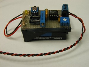
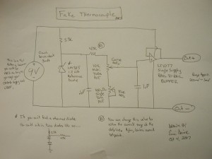
This was built as a one off using point to point wiring on a proto board. Do to the construction technique I have no board files, however I have included the schematic below in case you want to build one for yourself. The proto board was hot glued to a 9 volt battery holder, making the end result portable. Also, added a switch and led indicator so hopefully I won’t leave it on and run the battery down. Note the picture is a little outdated. The electrolytic caps are from a previous build in which I used an opamp that needed plus and minus supply voltage. In that build the 9V source was split with the electrolytics and some resistors in order to provide a plus and minus supply for the op amp. The current build uses a single supply op amp so the electrolytic caps and resistors seen in the photo are no longer needed.
How the Circuit Works
A reference voltage is set up through the 3.3k and the voltage reference diode. This provides an input to the 47k resistor that is always 1.2 volts even as the battery voltage sags. On the other side of the 47k are two potentiometers. The top one is a multi turn pot for course adjustment and the bottom is a single turn for fine adjustment. These pots plus the 47k divide the 1.2 reference on down to a range from 3mV to 200mV or so. The output from the wiper of the top most pot is fed into the op amp which acts as a buffer to isolate the load from the divider. The caps are there for smoothing and filtering. I am sure there are many improvements that could be made, but this is pretty quick to mock up and works for testing. It won’t hold the set point for long periods but, its more convenient then creating an actual heat source for your thermocouple.
Notes on Use
To use the device, connect the output of the supply to the point in your circuit where you would normally hook the thermocouple. It helps to hook a multimeter up in parallel with the output so that you can see the mV’s as you change the set points. Use the rough adjustment pot to get in the general ball park of the voltage you want then use the fine adjustment pot to get very close to the actual value you want to see. You can use thermocouple look up tables to check your circuit and see if its behaving like you think it should be.
Enjoy —ED
