Capacitive sensors of all sorts have been an interest of mine. They become interesting when you start to discover the huge variety of applications they are used for. While doing research for the new Control Panel in our airstream, I came across a couple of varieties of what appear to be a capacitive liquid level sensor for tanks. The TechEdge moda sensors appear to be capacitive based if you download there moda sensor manual and have a look.
These sensors incorporate two sheet aluminum plates that when stuck in proximity to one another on the tank form a small capacitor between them. Filling the tank with water changes the dielectric and therefor the capacitance. I decided to conduct a little experiment to see if I could do something similar.
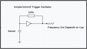 The above simple circuit uses a schmitt trigger gate to produce a square wave. Basically the cap charges and discharges through the gate and the resistor. This happens over and over and the period of the resulting square wave depends on the value of the cap and resistor combined. Its a very neat little circuit and can be used for all sorts of stuff.
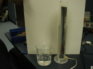
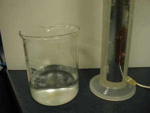
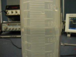
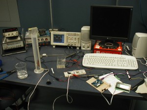
I took the basic circuit and replaced the capacitor with the aluminum plates on the tank. In my case I used a plastic 250 ml graduated cylinder. I cut a piece of of 2 inch aluminum foil tape in half and fixed one piece on either side of the flask. Then taped on wires with copper tape that has a conductive backing. That gave me a good connection to the aluminum foil tape without soldering. I measured the resistance to be less then an ohm so its making good contact.
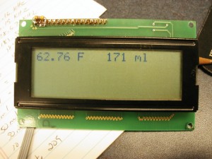
The output of the oscillator went to the scope and I was getting about 173kHz @ 250ml and about 208kHz @ 10ml so as the water level goes down the frequency goes up because the capacitor gets smaller. (I think thats right, scratches head) At any rate its quite a big difference in frequency and pretty easy to detect with a microcontroller. I quickly found a frequency measuring library for the Arduino and in a mere moments I had the display reading out the volume of the cylinder. Its amazing what you can do when you don’t have to re-invent the wheel and can instead use open source hardware and software. This would have taken me many hours to carve out on my own. Instead, it was almost trivial.
Really not to bad for a quick hack. I am sure that the frequency is going to drift around with temperature etc… How much I don’t know. Its a long way from really being able to climb under the trailer and install. If the tank were not so hard to access I would be tempted to install it as is and just see what happens. But, its a 50 gallon tank under the floor, and hard to get at. Perhaps next, I could play with a 50 gallon rain barrel. We’ll just have to see where it goes, but for now, it looks promising.
Pretty linear eh!!!

Can you provide the circuit you used for schmitt trigger or that not that critical?
Hi David,
I actually used a CD4093 nand gate wired as an inverter. The two inputs are tied together as one and the output is always opposite the input.
The circuit is the same as the one you see above. You could use a schmitt hex inverter also. The schmitt style gate is important because it has hysteresis. Check out this site for some more info on schmitt style oscillators.
http://talkingelectronics.com/pay/BEC-2/Page49.html
Let me know if you have anymore questions
Thanks for the great page. I would like to build a similar circuit to this, but using the mbed (LPC1768) instead of the arduino. I would really like to have accurate fluid level sensors, similar to what those MODA sensors can apparently do. Do you think TankEdge uses 74c14 chips (or similar) in their sensors?
Since I don’t have any nand gates and would have to purchase the necessary parts, would any of the many 74C14 chips do the trick? Is there anything else I’d need?
Hello Chris,
Ironically I just discovered a post from you on the mbed forum relating to this over the weekend.
I am glad you are interested in the circuit. Hopefully its about to move forward again with some custom made sensor plates. The aluminum foil tape that I used before worked well, however its hard to attach wires and make something thats durable and will last for a long time. My new plan is to fabricate some circuit boards for the sensors and see how that works. I’ll also need to do some testing for drift in different humidity and temperature conditions.
As for chips, really an inverter chip is the easiest. Something like a 74hc14 should work well. It must be of the Schmitt trigger type to form a simple oscillator, you can do the same thing with other non Schmitt trigger type chips but it takes more gates. Check out this page http://www.scienceprog.com/schmitt-trigger-vs-simple-inverter/ for more info on Schmitt Triggers. The real goal is get an oscillator going that uses the capacitance change coming from the sensor to change the frequency of the oscillator then use your microcontroller to measure the frequency.
As far as what actual chips, or even how the electronics work in other sensors like TankEdge, I have no idea. There are lots of ways to measure capacitance, this is just one of them.
Good luck building up your circuit. I would start with the oscillator first, get it going and if you have some way to measure frequency with a multimeter or other, watch the frequency change as you add water. Once that is working try and read the frequency with the microcontroller.
“Sneak up on it!” 😉
Keep me informed and let me know how you get along with it…
and please don’t hesitate to ask for more information…
Hi,
Thanks for the detailed reply. I’m very interested in building something that will give a more accurate reading on our holding tanks in our fifth wheel. Of course, you and I could both just buy the TankEdge system, or the SeeLevel II which apparently works on the same technology but that uses circuit boards instead of foil tape.
A project like this might force me to learn a ton of useful information along the way, and then I can create this to work exactly the way I’d like it to, assuming I can figure it all out.
My electronics skills need a lot of work, admittedly, but I can code. And I’m willing to learn whatever I need to.
To measure liquid level, is it necessary to use an oscillator circuit such as the above? Or, could a simple capacitance circuit do the trick? I already have a working and (apparently) accurate capacitance meter circuit.
Also, I’m guessing that this wouldn’t work on propane tanks because they’re made out of metal, right?
Chris
Hello Again Chris,
Yes I am pretty sure the TankEdge – SeaLevel etc works the same way, capacitive sensor and buying is, well, just not as much fun as building 😉 Plus if you build something you can expand, better display, pipe the tank levels to your phone via bluetooth, have your black water tank sending tweets etc… Worth it eh? 😉
Yes most of all you can learn a whole lot by working through a project like this. We are on the same page, I am sure of that.
You could forgo the oscillator circuit and do a direct measurement on an Analog to digital Port but it may not be as accurate as the frequency generator.
Basically you hook a digital output to the capacitor sensor on the tank. So you turn on 5 volts to it from the microcontroller by making the output pin go high. Then you monitor an Analog in port and and look for the voltage across the capacitor to cross a threshold. Mean while a timer is running in the background. When the cap crosses the threshold you look at the count in the timer and that number will relate to capacitance.
So a bigger number in your timer counter = a bigger capacitor. Keep in mind though these sensors are going to be small values in the picofarads most likely and the time constant is small.
You would also probably have to discharge your cap each time by bringing your output pin low for an instant reset your counter, then high and look for the threshold to cross. If you dig around on line for measuring capacitance with a microcontroller you should find lots of examples and code etc…
Right now I am thinking about making a circuit board to stick on the tank to use as a more robust sensor. I am also thinking about doing away with the inverter oscillator and build the oscillator around a PIC chip using a Schmitt trigger input and an interrupt on change.
Also thinking about an external Frequency to Voltage converter and then just using to the micro to measure the voltage instead of frequency but… I think it would be slick to keep it all down to one microcontroller and few if any external chips.
And you are correct, its not going to work well on metal. From what I can gather the way to measure propane tanks is via weight. I would like to do this too but trying to visualize some type of platform scale for the tanks is hard, particularly when bouncing up and down the road. Possibly you could lock out the scale mechanically then re engage at the camp site.
Lots of ideas, lets keep it rolling…
Well this is getting fun. I stopped in at my local electronics shop, and they didn’t have any 74HC14 ICs in stock, but did have the 74AC14, so I picked up a couple. As I write this, I’ve got one wired up on a breadboard with my best attempt to the circuit diagram at the top of the page.
Any chance you can post a pic of your breadboard? I realize the IC is different, but it might give me a better idea if I’m doing this correctly.
Also, although I’m using the mbed instead of the arduino, any chance you can post your code so I can (cheat and) adapt it?
Thanks,
Chris
Seems like that chip will work for you. Try a large cap like 100uF or so and a large resistor 100K or so, it should oscillate very slowly. You may be able to see it with a multimeter on the output.
The breadboard for this one is long gone 😉
As for the code I could post it but its probably pretty Arduino specific as 98 percent of it is the frequency library.
Right now the codes at work and I am at home, I won’t be around a terminal for the next couple days but let me know how you get along.
Here is a good overview of the RC time constant
http://www.wisc-online.com/objects/ViewObject.aspx?ID=DCE10604
The circuit should oscillate at the time constant of your resistor capacitor pair. Also if you need more help look around for info on Schmitt Trigger Oscillator, there is tons on line.
You will have to apply power to your chip. Pin 7 is ground and 14 is the supply, looks like 5 Volts. Then pick a gate to work with pins 1 and 2 should work put your resistor between them and your cap from pin 2 over to ground.
Remember whatever is on pin 1 the opposite should be on pin 2 its an inverter.
You count from the top left around to the top right counter clockwise if you look at the data sheet you will see the pinout.
Good luck,
ED
Hi ED,
Well, progress. I have the circuit working with capacitors. I’ve tried it with both 3.3V and 5V, and both work equally well. The larger the capacitor, the fewer oscillations per period of time. That’s exactly what we want. Initially, I hooked it up to my volt meter, but now I’ve got an ultra-bright LED indicating whether we’re low (off) or high (on, and blindingly so).
For added fun, looking at the connection diagram for this 74AC14 chip, I see that it has a total of 6 inverter gates, so grabbed another couple of capacitors, a few wires, resistors, and duplicated the circuit a couple more times. Woohoo, now all three LEDs are blinking at slightly different frequencies due to the different sizes of capacitors.
Next will be to write some frequency calculator code for the mbed. This is a very exciting little project. I can’t wait to try this out on a plastic water jug or bucket. That’ll probably have to wait though as I have a busy weekend ahead of me. I’ll let you know how that part goes.
Thanks again for your help.
Chris
Hi Ed,
Well, I hacked out some code that did a bunch of reads and calculated the frequency coming back off the chip. With actual capacitors, the results were pretty consistent, but once I switched over to various containers with foil tape on the side and wires stuck to the foil, the results were inconsistent; there was definitely an effect, but not predictably so. Adding water definitely changed the numbers coming out of the microprocessor, but not always in the right direction, or by an appropriate percentage.
Not sure how to eliminate the gremlins from the setup. I think I might try a different brand/kind of foil tape and see if that makes any difference. You had also mentioned using PCBs instead of foil tape, which sounds promising.
I would love to read more about this setup. I realize we’re exploiting physics here, but it seems like magic.
I’ll report back what I learn.
Cheers,
Chris
PS – went out in the trailer this past weekend. Weather was right around freezing, and on Saturday we woke up to a bit of snow. Had a great time though.
Sounds like you are getting close.
Honestly I really cheated by just using someone else’s frequency counting code with the Arduinio. It was a quick hack to test the concept. When I do it again I will be using a PIC chip, probably a 12F629 or such, 1 for each sensor.
A lot of microcontrollers have a “ClockIN” pin you can turn on. This external pin then updates a clock register every time the sensor changes state. Then you set another internal timer to interrupt on roll over. Generally the internal interrupt timer is smaller then the outer one for instance a 16bit timer and an 8bit timer.
So… when the internal timer overflows it takes you to the interrupt subroutine where you read the count on the external timer and then reset it. That number can be averaged or whatever you need, you really don’t need to convert to frequency, you could just use the pulse count by itself as a judge of liquid level.
As for the sensor, I definitely think the circuit boards are going to be a big help. For one just for ruggedness and wire connection. At these small capacitance values ANYTHING can influence them. Shielding the wire and grounding the shield would help, also twisting the wire.
In my initial setup even approaching the table would change the frequency value slightly.
If you can find or gain access to a frequency counter or a scope it would be a big help to you. Just play with your sensor and the frequency counter until you get something consistent with your sensor setup. Then try and marry that to the microcontroller. Otherwise you may spend a lot of time just guessing whats going on.
Oh and YES on the 74AC14 you can get 6 discreet free running oscillators. Its really cool, I used this circuit to pule 6 strings of different LEDs for a sign once and it worked well. I spread the LEDs out all over the front and connected them randomly to the 6 different busses and wahla beautiful slow changing twinkling LEDs. Pretty neat all the things you can do with this simple circuit.
http://www.robotroom.com/PWM.html
If the counting or reading the frequency pulses becomes a chore you may want to consider a frequency to voltage converter chip or possibly a digital counter chip like a decade counter.
You will be so happy when you get it working…
PS: We went out too 😉 We are down south though, perfect weather, went to Skidaway outside Savannah Georgia old Live Oaks and Spanish moss wonderful. No bugs this time of year. Would have been cool to know how much was in my tanks 😉
OH and the guy with the Zero Characters Left blog turned me onto this:
Nuts and Volts Liquid Level Meter
Any further results with the PCB? Are you getting more consistent readings?
Sorry to say Zeph, I have dropped the ball, and it has rolled out of reach. I am still playing with capacitive sensors, but of a different sort. Check out symcdc.com thats were I have been spending all of my efforts lately. Hopefully I can get back to the tank sensors before to long but for right now its on the back burner.
Hi Ed.
Do you have a schematic diagram for this? I am planning to replicate this project, and I am having a hard time knowing what components to use. Thanks!
Sorry no schematic, other then the one one for the oscillator. You could use a 74HC14 HEX inverter. The tank sensor acts as a capacitor. The capacitor changes with water level. The change in capacitance changes the frequency of the oscillator. After I got the frequency to change with water level, I used a micro controller to measure the frequency and report the volume. Check this page out for description of a square wave oscillator. Replace the capacitor in the circuit with your tank sensor.
Hi ednspace,
i try make same Capacitive Level Sensor and i have some trouble. My container is 150ml measuring cylinders (37mm ID) and electrodes is 2x aluminium tape (20x150mm). My DMM show only 40pF between empty/full cylinder, it’s normal ? or it’s very small difference. Also interests me, how much influence will have the acidity or alkalinity of water.
Thanks
Probably about right, its going to be in the pF but, by using the oscillator circuit above you should see a large enough change in frequency to measure the difference.
Dear all,
I have tried for level sensor. An oscillator , and PIC microcontroller. It works. but there is problem of TEMPERATURE COMPENSATION.
I do not get same reading in afternoon and morning.
Have you faced this problem ?
I have not seen this but I don’t doubt it. So far I have not run a long term test. Its possible that the Pics internal oscillator is drifting since it is an RC time clock and has a temperature sensitive resistor. If the internal oscillator changes speed then that would effect your ability to accurately measure the oscillator that is coming from your sensor. Also, the same thing goes for the resistor in the sensor circuit. Another thought is the container itself might be changing shape over time do to temperature and moving the plates closer or further apart.
Possibly you could try a stable oscillator that mimics the sensor output and let run over night to see which is which, but if it has a resistor you are kind of back where you started. You could try directly heating the resistor in the sensor circuit. Or, heat up the water in the container, or drop in an ice cube and see if it radically changes the reading. I suppose its possible the temperature is changing the dielectric of the water, but I am unsure? Interesting problem. Let me know how your progress goes, also I’d love to see a graph of the temperature change verses the frequency change coming from the sensor.
Hello ednspace,
First of all thank you for publishing your interesting experiment which would be helpful to many.
What would be the result by using Arduino’s CapSense library?
http://playground.arduino.cc//Main/CapacitiveSensor?from=Main.CapSense
This does not need a square wave oscillator. Example at instructables’s site:
http://www.instructables.com/id/Building-a-Capacitive-Liquid-Sensor/
For a large tank (6 feet tall), which method would produce better result, you think?
I have read that you are no longer involved in this. However it would be good if you can say something from your previous experience. This will help to start with the right direction and avoid testing :).
Best regards.
Its possible that the cap sense library would work. I had a quick glance and found this method
long capacitiveSensor(byte samples)It seems like with that one you give the number of samples you want to take and it returns a number that represents the “capacitance”
I think the way this type of setup works and possibly the one you mentioned on instructables, is to turn on a pin and start a timer, then you wait for the cap to cross a threshold and then read the timer. The timer relates to capacitance based time constant of the cap.
With the liquid level sensor the cap values are going to be small and you wont have much time to charge, change in capacitance of a metal foil plate do to a body being near is small too so…. It may well work. I would think, off the cuff using the oscillator and measuring frequency may give you higher resolution but… YMV
It would certainly be easy to try if you have an arduino handy. Just tape on the strips of foil ground one and run the other to the sense resistor. Put the long
capacitiveSensor(byte samples)in a loop and print that out to the screen. Add water and see if it changes.Let me know what you discover, I still really do need to build some tank sensors for the trailer which was the whole original point of this. There is an on board Arduino but I am thinking about changing it out for a Raspi
Lots of luck and thanks for comment, please let me know what you discover and if you can what your application is…
Thanks a lot ednspace. I shall inform you the result.
I am also happy to know that you are returning to it again. Since you have already done many testing and know it better, hope we would get the best ready-made solution (avoiding long testing :)).
By the way, I wish to ask one more question although not related to water level measuring. You may have seen the vehicle security alarm, which is activated if touched. The arduino CapSense library can also detect ‘touch’ on small foil. Will it be able to detect touch on a car body? If not, how does the vehicle security alarm work (these are cheap)?
Thanks again.
I have tested the CapSense and the method for Basic Stamp (Nuts and Volts pdf) on this page.
Among these 2 methods, I like the Basic Stamp way – almost linear.
I did not like the CapSense much. But it works. It has ground issue. Sometimes reading shows a high value suddenly, and then stays on that value (changes a little).
All the tests were done with a plastic water jug, no real big water tank.
Best regards.
Hello,
Can you show me how this circuit would work with the use of deflection bridge.
Thanks.
Sorry, not sure what you mean by deflection bridge, do you mean a standard bridge circuit?
If so I think this circuit would be hard to balance as it is putting out a frequency based on capacitance.
Hi, I am also working on a water level sensing concept using capacitive sense. In my project i want that the sensor will indicate the water at 3 level low medium and full in a reserviour. I was thinking that if i can use a capacitive pad on a pcb and hold that pcb with a reserviour on outside wall. then as soon water level increases , capacitance changes.
Is the above approach is good to go. I have experimented the concept with capacitve touch pcb and hold it along the bottle and measure the change in capacitance.
Does the circuit suitable to be the outdoor rain gauge ?
Does the outdoor temperature affecting its accuracy ?
As far as I know it would work well outside, but you may need to seal off your tape so that you don’t get bridging and protect your connectors. As far has heating and cooling effecting, it may, best to let it run through a full day cycle and record your readings without the influence of water. I suspect you will see some frequency drift, but it shouldn’t be to much, you may even be able to compensate in software, if you have a temperature measurement to compare with.
Thank you very much, thus i will try to do it as RainFall Measurement Gadget.
Great, let me know how it turns out, I would be very interested to see this circuit put to practical use.
Hi,
Is it possible to just use copper plates with the wires soldered onto it?
I mean, instead of the aluminium tape and copper tape….there seems to be wrong in my circuit and the value only changes when i touch the wires….
Copper plates should work fine, you are really just making the two plates of the capacitor and changing the dielectric in the middle by adding or removing the water. Try replacing the sense capacitor with a regular capacitor like a .1uF or so. Then possibly double it by adding another in parallel, you should see a frequency shift, it would at least help you troubleshoot your circuit and let you know if its working. Then go back to your sense capacitor and try adding and removing the water.
Greetings ednspace
I am currently developing a like in your project a level meter with capacitive sensor (copper tape) with atmel, but unfortunately the measurement does not do it correctly, I have more than all doubts in the part of Hardware, because I’m not very clear when I read your explanation of how. That is po much I’ve been programming, the measurement misses me, gives me concretely as shown in the photo of your experiment, which is exactly what I need.
Do you think you could help me? my email is rhayza@gmail.com
Thank
Greetings ednspace
I’m developing a project very similar to yours, but measuring that throws me is wrong, because it has a lot of interference, could you help me? or indicate or so you did not have tantan interference in the measurement.
thanks
Hello,
Sorry so late in the reply. Don’t check the blog much these days. Whats up with the interference you are seeing. Do you have the square wave generator part of the circuit working? Do you have a way to verify the frequency like an oscilloscope or frequency counter?
Let me know and I can try and help…
I have interference issues as well. It will jump around widely. I’m still trying to narrow it down. It does this with a glass jar and with a plastic container. It doesn’t do this with a little capacitor that I have laying around very much. I may get a number or two off, which roughly translates to about 10-30 hz difference. I’m running a counter at roughly once per second using a pic18f25k80. I’m not quite sure how to trouble shoot this. Oddly enough it seems to work without the second plate of the capacitor, I’m starting to think they are not interacting with each other, and instead with something else. This unknown thing may be causing my issue as well as Rhayza’s.
I do not know the value of the homemade cap, the one with the strips on the bottle is going to be very small, like in the low pico farads. It will cause the circuit to oscillate very fast.
When you say you are checking every second or so, what is the sample rate when you are checking. Are you just counting the number of falling or rising edges in a certain period of time?
One way to verify would be to do the math for the time constant of your RC network and see if it matches your known cap value. Then put a slightly bigger cap in and see if it changes as you think it should. That would help you determine if your counter was working.
The bottle cap should be fairly stable if the capacitance around it is not changing much though the frequency will be fast.
temperature compensation ? create a second and duplicate circuit.
use a fixed capacitor and install it on the same board that is next to the tank. both will change with temperature, so you have a simple temperature reference. option 2) set the second circuit to be equal to the empty tank circuit. both have the same frequency, then measure the difference. both will float with temperature, but the output would be the tank level.
Ya i also read Your Post and i want to know how it turns out, I would so much excited to see this circuit put to practical use. hope we would get an best possible solution from avoiding long testing.
http://www.rmcybernetics.com/
why can you not reuse the “copper Moda Sensor pads”? from the water holding tanks. what, if any special treatment are on the pads?
Does this method work if i try to measure the water flow inside a tube by using 2 parallel plate attached to each side of the tube ?
I think you could tell if your liquid was in the pipe but I do not think you could tell the flow rate with this method.
Hello guys, for the schmitt trigger circuit, can we use the 555 timer IC to blink the light? the light will blink faster or slower depends on the capacitance ?
Yes it sounds like it might work. Give it a shot. You would have to slow the frequency down with the 555. You might need to build a frequency divider.