A touch plate or zero plate is used to zero the toolbit on the Z-axis. I first saw this in a Hackaday post about quick CNC setup routines. This person uses a usb pendant, laser and touch plate to very quickly set up a piece of work in the machine. Here is a link to the video and post…
My machine would really benefit from this setup. First the machine is far enough away from the computer that I can’t easily see whats going on (I think this must change anyway), second the spindle I am using has a brush on the bottom that blocks the view of the bit. The brush is nice, as it locks in debris and helps the vacuum remove chips. However, it touches down first before the bit makes contact and makes it hard to tell when the bit reaches the surface of the work.
To make this work you need an input pin on the parallel port pulled high and then connect this input pin to a conductive plate. When the bit, which is at ground potential, touches the plate, it will pull the pin low and signify that the top of the work has been reached, just compensate for the thickness of the plate in software.
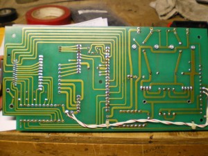
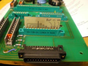
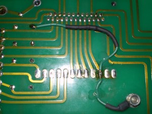
I had to pull the mother board out in order to see the bottom of the connector, find a 5 volt rail and map my pull-up resistor to one of the connector pins. I have been wanting to pull this board off for a while just so I could get a picture of the underside.
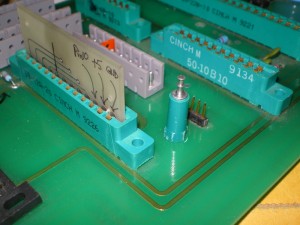
Pin 10 goes to the small jumper board but no where else 🙂 Its also an EMC software input.
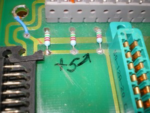
I found a 5 volt rail close by
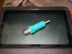
There are number of these old binding post in my parts bin, so I decided to use one, had to drill a hole in the board, however I love the way it matches the connectors.
I wired the connector pin for the parallel port to the 5 volt rail through a 10k pullup resistor and wired the connector pin to the binding post. Now all I have to do is bring the binding post low and the probe pin output should change, indicting the bit has reached the surface of the plate.
Looks kind of orginal from the top, hope it works…
Tags: OZO CNC Rebuild
