Spent some more time with the LS7262 spindle motor chip datasheet today. Used the drawing I made previously with the pinouts for the board and with the datasheet I tried to figure out what signals I should see on the various pins.
The first thing I noticed was that the LS7262 is supposed to be for transistors and the LS7260 is supposed to be for FETs, this is odd since the main power components on my board are obviously FETs. Still there are some transistors (possibly gate drivers) in front of the FETs.
I noted that CS1 and CS2 where both tied low and that I was only showing two Sense pins coming out of the board. Turned out that this was the configuration for Four Phase Operation (page 5).
Also, the Enable pin is active High and Low Disables the output.
The chip needs:
Voltage for a Logic 1 (High) VSS-1.5V to VSS
Voltage for a Logic 0 (Low) 0V
Probing around this evening:
VSS Pin 11 to Ground: 15.0V with Small encoder card Removed
14.2V with encoder card in.
Common Pin 5 to Ground: Same as above
Brake Pin 9 to Ground: 0V
Enable Pin 10 to Ground: .5V with encoder card in 15 Volts with it out. (Hmmm!!!)
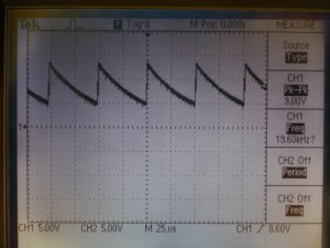
Ocillator Pin 14 to Ground: Sawtooth waveform Peak at 13.4V Floating on 4.60V (Perfect, I think)
Also, during all this probing, I noticed that the electric air valve that I think controls the spindle collet, engages with the button on the front panel only when the small encoder card is in the machines.
So, after I probe the signals and realize that all the signals are basically there, I try the spindle with out the small encoder card installed so that Enable is on and not being held low by the card. No joy!
I decide to have a look at Vtrip and it is low. This would indicate the spindle should be running at full speed. I remembered at this point, somehow, that when we moved the machine a fuse cap had fallen off of one of the two fuses on the back of the machine. I had picked up the cap and stuck it back on, at the time it hadn’t seemed to fit well. Reinvestigating it seemed that there was a spring missing and the fuse was fitting very loose in the fuse casing. Digging around in the surplus pile I found a small spring that fit in the cap. Once installed I tried starting the machine again, and much to my delight, the spindle motor spun up to life. Sweet!!!
It seems there is a speed controller as part of the small encoder board, as when its installed the Spindle spins up however slows down and stops shortly. Vtrip pin, which controls the PWM starts about 2 volts and then climbs to around 11.00 volt disabling the spindle.
Looks like the next step in all this is going to be to figure out the encoder board. Still if I want to run the machine with the spindle now, I could do it with a small breakout board. Transistor to control the enable pin and a voltage divider with a pot for the spindle speed control. Looks like I am close to actually being able to cut something.
Scope Image of the Oscillator:
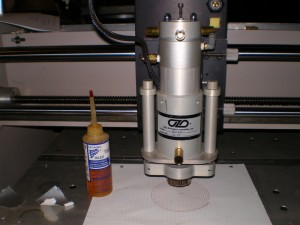
Spindle:
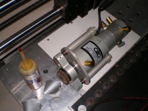
Spindle:
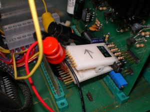
Test Jig:
Tags: OZO CNC Rebuild


