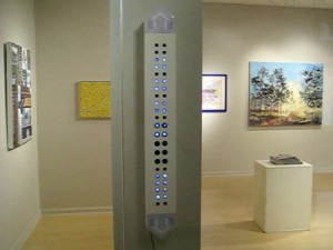
A friend and I spent some time a few months ago collaborating on an art piece. His Light Boxes usually consist of some translucent material, film, printed transparency, large prints, envirotex casts etc, that are mounted in or on a box, with a light behind. Sometimes the light moves, sometimes the piece moves, sometimes both are static. We decided to see if we could combine our skills and come up with something a little more dynamic, possibly even something that people viewing the piece could interact with.
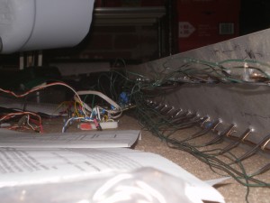
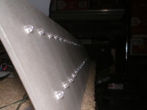
The “box” in this case was a rectangle with 44 small circular cutouts arranged in two columns. Behind each cutout he affixed a slide from an old collection, mostly of houses, family life etc… Behind each slide we placed a white LED so that when it was energized it illuminated the slide and the viewer could see the slide.
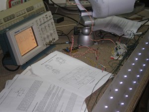
Craig worked on the presentation, the box, the slides, the theme and assisted me with the wiring. I was responsible for designing the control electronics, the sensor inputs, and the coding of microcontroller for the patterns. The build took us several sessions over a few months, sometimes working independently, sometimes in tandem. It was interesting to see the work evolve from a rough sketch to a finished art object.
Craig has a great write up on the finished piece posted on his website. For my part I will try an explain a little bit of the electronics.
We wanted the ability to control each LED independently, thinking that would give us the most flexibility to use the box as a display for whatever sort of sensor input we could dream up. For this part I chose to use an old favorite chip of mine, MAX7219. Its a 7 digit 7 segment control chip, but also has a dot mode that when exploited allows you to multiplex up to 64 individual LEDs.
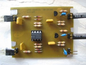
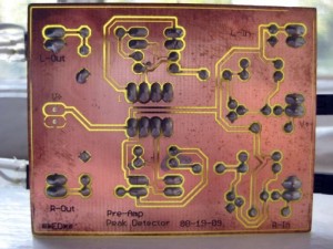
For the sensors we went with something basic electret microphones. We used two for stereo inputs, one microphone for each column of LEDs. These circuits basically consisted of an electret microphone, an amplifier, and a peek detector. I could have sampled the signals from the microphones skipping the peek detector and used some digital filtering and averaging to figure out the peek. At the time it seemed easier to just bang it out in analog circuitry. It cost me more in components and layout time, but it was simpler in the moment, and I didn’t have to finesse around for hours with wacky controller code trying to figure out why the display was glitchy. There was enough of that sort of thing going around the bend as it was 😉
For the brains I used a garden variety PIC16F88 microcontroller. The microcontroller samples the peek detectors, and tells the MAX chip which leds to turn on. The microcontroller also drives the Morse code pattern on the display when the piece is not in VU meter mode, basically whenever its surroundings have been quite for a while. In the future we may try and incorporate some more patterns or sensors.
Here are some photos of the inside of the piece, the parts that I worked on, check out Craigs write up for a video of the piece in action.
