Archive for the ‘OZO CNC Rebuild’ Category

Impasse

Friday, June 6th, 2008

Reviewing the EMC2 manual it seems that pins 18-25 on the parallel port or always ground. The signals I want access to next on the OZO are the encoders and the spindle control. Unfortunately the encoder signals look mapped to Parallel 20,23,24 and the likely spindle control is on Pin 11.

These pins are not going to work with the Parallel port in the computer. I may not even have enough I/O on the port to completely control this machine, however, what I really need next is spindle control, at least on off. Looks like the OZO may have had a proprietary card in the computer after all.

The new plan is to build a small converter board. I am hoping to use two wire wrap parallel port sockets, plug one end into the OZO and then map across to the plug that will connect to the computer. This way I can remap some of the OZO signals to the computer and have access to them at the port for probing etc…

We shall see!

Encoder Board

Friday, June 6th, 2008

Tried to do a bit of reverse engineering on the encoder board. Pin 1 starts on the end of the board that bolts to the machine.

Pin Signal
1 Routes to 1B and 8B on Spindle Board Ground FWD/REV
2 Signal in from actual encoder routes toSN74LS123N
3 Signal out from encoder board to Pin 20 Parallel
4 Signal in from actual encoder routes to SN74LS123N
5 Signal out from encoder board to Pin 23 Parallel
6 Signal in from actual encoder routes to SN74LS123N
7 Signal out from encoder board to Pin 24 Parallel
8 Routes to Spindle Board Pin 6B V-
9 Unknown
10 Unknown
11 Routes to Parallel Port Pin 1 and Pin 12 probable Ground
12 Routes to 1B and 8B on Spindle Board Ground FWD/REV
13 Unknown
14 Unknown
15 Routes to Spindle Board Pin 4B and 10B V+ Positive Voltage
16 Unknown
17 Routes to Spindle Board Pin 7B Vtrip
18 Routes to Spindle Board through 4.7K to Pin 9B Enable
19 Routes Parallel Port Pin 11 *****Possible Control signal for Spindle *******
20 Routes to Spindle Board Pin 2B (S1 Signal)
21 Routes to Spindle Board Pin 3B (S2 Signal)
22 Routes to 1B and 8B on Spindle Board Ground FWD/REV

Links to the data sheets for the major players on the board:

DM74LS123 Dual Retriggerable One-Shot, there are two of these, probably handling the signals from the encoders. The Q outputs of these go to the Parallel port and the B inputs go to the encoders, not sure yet how this works.

MC1458 High Performance Dual OpAmps, most likely controlling the speed of the spindle, there are two on this board.

CD4070BC Quad 2-Input Exclusive Or Gate, somehow tied with Enabling the Spindle, might be a phase detector? Square wave to enable spindle, I dunno, it gets confusing pretty quick around this thing.

The Spindle Moves

Wednesday, June 4th, 2008

Spent some more time with the LS7262 spindle motor chip datasheet today.  Used the drawing I made previously with the pinouts for the board and with the datasheet I tried to figure out what signals I should see on the various pins.

The first thing I noticed was that the LS7262 is supposed to be for transistors and the LS7260 is supposed to be for FETs, this is odd since the main power components on my board are obviously FETs.  Still there are some transistors (possibly gate drivers) in front of the FETs.

I noted that CS1 and CS2 where both tied low and that I was only showing two Sense pins coming out of the board.  Turned out that this was the configuration for Four Phase Operation (page 5).

Also, the Enable pin is active High and Low Disables the output.

The chip needs:

Voltage for a Logic 1 (High)  VSS-1.5V to VSS

Voltage for a Logic 0 (Low) 0V

Probing around this evening:

VSS Pin 11 to Ground: 15.0V with Small encoder card Removed

14.2V with encoder card in.

Common Pin 5 to Ground: Same as above

Brake Pin 9 to Ground: 0V

Enable Pin 10 to Ground: .5V with encoder card in 15 Volts with it out. (Hmmm!!!)

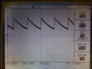
Ocillator Pin 14 to Ground: Sawtooth waveform Peak at 13.4V Floating on 4.60V (Perfect, I think)

Also, during all this probing, I noticed that the electric air valve that I think controls the spindle collet, engages with the button on the front panel only when the small encoder card is in the machines.

So, after I probe the signals and realize that all the signals are basically there, I try the spindle with out the small encoder card installed so that Enable is on and not being held low by the card.  No joy!

I decide to have a look at Vtrip and it is low.  This would indicate the spindle should be running at full speed.  I remembered at this point, somehow, that when we moved the machine a fuse cap had fallen off of one of the two fuses on the back of the machine.  I had picked up the cap and stuck it back on, at the time it hadn’t seemed to fit well.  Reinvestigating it seemed that there was a spring missing and the fuse was fitting very loose in the fuse casing.  Digging around in the surplus pile I found a small spring that fit in the cap. Once installed I tried starting the machine again, and much to my delight, the spindle motor spun up to life.  Sweet!!!

It seems there is a speed controller as part of the small encoder board, as when its installed the Spindle spins up however slows down and stops shortly.  Vtrip pin, which controls the PWM starts about 2 volts and then climbs to around 11.00 volt disabling the spindle.

Looks like the next step in all this is going to be to figure out the encoder board.  Still if I want to run the machine with the spindle now, I could do it with a small breakout board.  Transistor to control the enable pin and a voltage divider with a pot for the spindle speed control.  Looks like I am close to actually being able to cut something.

Scope Image of the Oscillator:
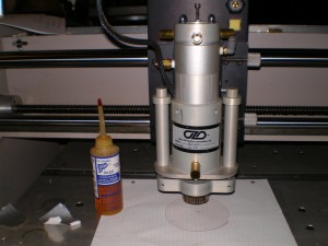
Spindle:
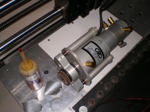
Spindle:
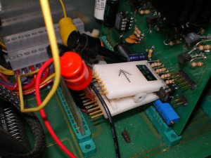
Test Jig:
Spindle Motor Controller

Friday, May 30th, 2008

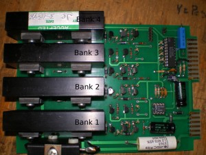
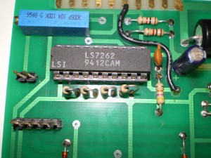
This OZO has a spindle motor, with a proprietery controller card.  This evening I took the first stab at trying to reverse engineer this circuit card.  From my research so far, I think that it may be possible.  There are 8 output devices all appear to be the same 32N20E, these are 32Amp 200Volt Power FETS, WOW!

There is an LS7262 brushless motor controller chip and a 555 timer which may provide the oscillator input for the servo controller chip.

This is a picture of the Board with the IO pins labled:

Close up of the Board with Pins Labled

Pin out:

The bottom right 5 card edge connectors seem to be associated with the output drive to the motor.

1A Power for the motor (Probably High Voltage like 30 Volts)

2A Fat Trace to FET Bank 4

3A Fat Trace to FET Bank 3

4A Fat Trace to FET Bank 2

5A Fat Trace to FET Bank 1

6A Ground (Also connects to 1B)

The upper card edge connector appears to be IO for the LS7262 Chip

1B Ground (Also connects to 6A)

2B Connects to S1 on LS7262 (PIN 15)

3B Connects to S2 on LS7262 (PIN 16)

4B VSS which is actually V+ for the LS7262 (PIN 11)

5B Brake of the LS7262 (PIN 9)

6B -V of the LS7262 (PIN 18) Also connects to the CS1 and CS2 and Ground

7B VTRIP of LS7262 (PIN 13)

8B FWD/REV of LS7262 (PIN 19)

9B ENABLE of LS7262 (PIN 10)

10B V+ also goes through Pot to open jumper pin to CS1

It will take some more reading of the data sheet to figure out what signals EMC needs to send to control the servo.  It seems like it revolves around the Vtrip pin as far as speed control.  That pin seems to go to one of the IO pins on the other proprietery card.  It will take some more time to begin to understand that card.  I thought that it was mainly centered around the  encoders and limit switches, now I am beginning to question that assumption.

Its nice to think there may at least be hope of getting the existing orginal spindle going again.  We shall see…

Tuning the Machine

Thursday, May 29th, 2008

OK, now to get the OZO purring like it otter…

First I visited EMC Wiki and followed the latency test directions.

These directions are basically the same ones in the integrators manual, however there are a couple of new wizards mentioned on the Wiki page, that came out with release 2.2.2. I first ran the latency test the old fashioned way, and then the newer way by just typing latency-test into a terminal.

The results:

Old way reports 22,778 nS

New way jitter reports 20,020 nS

I decided that I would take an average 20,544 nS and round down to 21 uS

Now to figure out thread pitch, using the method described here I came up with:

X Pitch Count=5 Pitch=.200 in.

Y Pitch Count=5 Pitch=.200 in.

Z Pitch Count=8 Pitch=.125 in.

My motors are 1.8 degree per step 200 steps per revolution.

From the best  manual I could find, my stepper controller requires 15 uS step hold time, there is no timing information for the direction pin. So, rather then configure step time, step space, direction hold, direction setup times individually, I will use 15uS + 21uS = 36uS as the Base Period for now.

The driver I have can only run full step and half step, I am going to assume half step for now as I can not easily access the jumpers in order to verify.

Next I ran the stepconf wizard and set the IO pins for the parallel port and tried to fine tune and measure each axis.  I followed the directions in this PDF as well as this Tutorial.  There was some error with the Z travel distance and I had to run the program again after the initial configuration.  I was able to edit just the sections of the Z axis that I wished with out issue.  Really nice job on the Wizard/Druid thanks to EMC team.

In the end I decided on 2 revolutions per inch on the Z-Axis, had to open up the motor housing, measure with a caliper and then rotate the stepper shaft by hand.  Seems to be scaled right with what I can measure at this point.

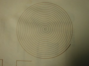
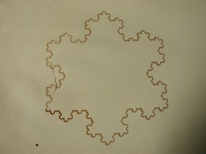
I plotted a couple of the examples from the EMC examples directory just try everything and this is what the machine drew, using the pen tool on the Z-axis.

It Moves…

Tuesday, May 20th, 2008

Just a quick post, I am very happy.

This evening I finished tracing out the main signals to the parallel port. Copied the default files from emc sample_configs into my home directory and edited the default pinout hal file to reflect my findings. Changed just a couple of things in the default stepper ini mostly just to reflect filenames, and …

Figured what the heck, lets give it a go. I was a little nervous about trying to run the machine without isolation, and the ground traces don’t line up between the computer and the machine, but hey!!!

It worked!!!

I had to invert the direction pin for the X axis, but that was a simple edit of the pinout file. Sweet! I ran the test gcode, and moved the machine around manually. Its way out of tune, the scale is way off. However, all of that can be fixed. At least it moves, and thats a very big deal indeed!

EMC Documentation list the very nice User Manual as Well as Integrators Manual. The Integrators manual has a section on tuning stepper motors.

Some Notes from a person explaining how they set up there steppers and adjusted for scale. Seems like the variable to change is INPUT_SCALE in the ini file.

EMC Configuration

Sunday, May 18th, 2008

I have decided to use linux EMC as the initial control software.  First I love linux, second this is fantastic software for machine control.  It runs with on top of a real time kernel and has a nice GUI interface called axis.  As I ramp up on GCODE and CAM/CAD software I have been using AXIS to simulate my produced code.  Its all been working very well.  I have a bit of experience with EMC in the past, using it to help some Senior Design Students retrofit an old StarTurn CNC Lathe.  So, for now its an obvious choice for machine control.  I’ll use this post to document some of the install notes and configuration changes.

Using Ubuntu Dapper LTS for now, even though Hardy Heron LTS is recently out.  My machine for control purposes right now is an older 700Mhz Pentium.  Dapper has been running on this machine for over a year, so for now, just installing EMC along side, will reboot into the realtime kernel to control the machine.

First Step:

Used the install script from the EMC website, changed permissions to executable and it ran fine rebooting into 2.6-15 Magma realtime kernel EMC2 works!

Next Step:

Review standard_pinout.hal to see how its configured by default standard_pinout

A little Research

Sunday, May 18th, 2008
  • Proxy Statement This is Document outlining the exchange of the company to Jot Engineering gives interesting details about the number of this type of machine and cost etc…
  • OZO Support Some ex OZO technicians that will repair and work on these machines, they have a history page images of the machines and, sell replacement parts, software.
  • Servo Spindle Motor Driver Chip DataSheet link for the chip that controls the spindle motor drive electronics
  • Anaheim Automation The people that make the stepper Motor Controller Module
  • User Manual Link to a user manual that is very similar to the controller box in the OZO machine not the same one, however email to Anaheim yielded no return on the exact model number of the box thats in the machine, so far this is the best reference for the hookup.
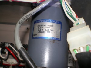
  • Stepper Motor A catalog from EADmotors Eastern Air Devices, list the stepper motor in the machine. model LA23DGK-23 in unipolar configuration (6 leads) (6.00 VDC) (1.76 amps) (3.40 ohms) (8.4 mH) (168 oz-inch) in bipolar configuration (8.50 VDC) (1.25 amps) (6.80 ohms) (33.4 mH) (210 oz-inch)  Not sure right now the motors are in bipolar or unipolar configuration.
  • 4N26 Opto-Isolator the chip I plan on using to isolate the computer parallel port from the machine controller.  Mainly just because I have some.
  • Parallel Port Link to the Hardware Book parallel port pinout page
  • A Chart of the Pin Out of the Ozo Machine as I manage to trace out the existing connections
Pin Parallel Port OZO Machine
1 Ground Ground (Wired to Pin 1 OZO)
2 N.C. Red Unused (Wire runs to near controller N.C)
3 N.C. Purple Unused (Wire runs to near controller N.C)
4 Clock (Z-Axis) Red Clock (Z-Axis) (Wired to Pin 4 OZO
5 Direction (Z-Axis) Purple Direction (Z-Axis) (Wired to Pin 5 OZO
6 Clock (X-Axis) Red Clock (X-Axis) (Wired to Pin 6 OZO
7 Direction (X-Axis) Purple Direction (X-Axis) (Wired to Pin 7 OZO
8 Clock (Y-Axis) Red Clock (Y-Axis) (Wired to Pin 8 OZO
9 Direction (Y-Axis) Purple Direction (Y-Axis) (Wired to Pin 9 OZO
10 Probe Input Probe Input (Wired to Pin 10 OZO)
11 Y Home Switch High Open Low Closed N.C.
12 X Home Switch High Open Low Closed N.C.
13 Z Home Switch High Open Low Closed N.C.
14 N.C. Y Home Switch (Wired to Pin 11 computer)
15 N.C. X Home Switch (Wired to Pin 12 computer)
16 N.C. Z Home Switch (Wired to Pin 13 computer)
17 N.C. N.C.
18 GND N.C.
19 GND N.C.
20 GND N.C.
21 GND N.C.
22 GND N.C.
23 GND N.C.
24 GND N.C.
25 GND N.C.

Lets See Whats inside

Sunday, May 18th, 2008

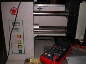
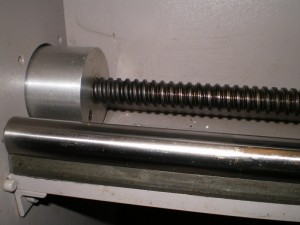
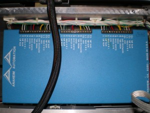
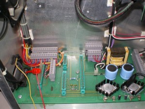
Just a few shots to document the innards of the machine. Whats really fantastic is that I found a 3rd party stepper motor driver. This should make motor drive interface at least possible to sort out. Really, I was expecting to find some proprietary hardware controlling the stepper motors, this find is a huge bonus. There is some custom hardware for the spindle motor controller, however at least one of the chips gives a great clue as to how the board might be set up. Some images to clarify the insides.

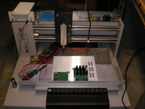
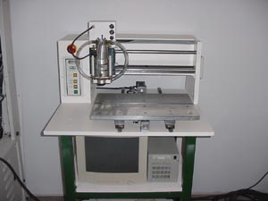
Front view with covers off testing stages:

Front Panel:

Front Panel

Close up of one of the stages drive mechanism

Stepper Motor

Controller Aneheim Automation

Spindle Motor Controller Chip

Main Board

Note Sheet

–Begin CNC Rebuild–

Sunday, May 18th, 2008

First Steps:

Built Metal and Wood Platform with Castors to support the machine

Cleared a Path to the machine in the Tin Shed

Friends gathered to help move the machine (very exciting)

Open machine to see whats inside…

Similar Machine Model 18